Our Port Flow Analyzer for flow bench testing has several features for making several measurements of cylinder head performance. For head flow, pretty much anything that improves CFM flow improves the HP potential of the head. But after measuring CFM, there are several other measurements which can give better insight into one particular head runs well on the dyno or the track, and another head with equal or sometimes even less flow can run much stronger. These are the hard earned “black arts” of head porting which many engine builders are reluctant to share. Questions these engine builders are looking to answer include:
1) Have you given up too much port velocity for improving CFM flow? This is pretty much dictated by port volume. An engine with too much port volume has low velocities and will not make good torque at midrange RPM. There are many simplistic “rules of thumb” on this, but the best way to know if you have too much port volume is with a sophisticated engine simulation program like Engine Analyzer Pro.
It can read our Port Flow Analyzer files which contain both CFM flow and port volumes and tell you how the head will likely perform at various RPMs. A particular head may have too much port volume for a smaller CID or shorter runners, but at a different RPM, runner length, cam, etc., it may run real strong. A simulation program will let you investigate all these trade offs.
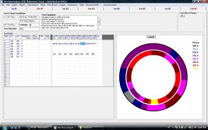
2) Where is the port velocity highest? This is called “port mapping” and
uses velocity probes to construct a map of high and low velocity areas.
There is little universal agreement about how a port map should look. But
if the port maps are different between a good and bad head, it gives you
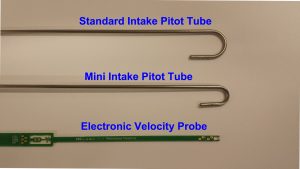
insight on where to look. Pitot tubes are the standard method, but are
quite large and bulky for measuring intake flow, where they must have a 180
deg bend so the tip faces the incoming flow. They are hard to get into
tight spaces, or into small or short ports. We have our Mini Intake tubes,
which are better, but still relatively large. This year we have developed
our Electronic Velocity Probe which are MUCH smaller and a big leap forward
in technology.
3) Are we using all of the valve to allow flow, or is all the flow going
through just the back half of the valve? To know this, you need to measure
flow velocity around the entire edge of the valve. Ideally you will see
about the same velocity around all 360 degrees of the valve’s head. If you
find low velocity areas, that tells you you could better use the entire
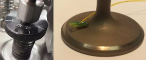
valve flow area if you got more flow into that area. The Plus version of
the Electronic Velocity Probe lets you mount just the tip close to the edge
of your valve. You can now rotate the valve at a particular lift and find
“lazy” low velocity areas.
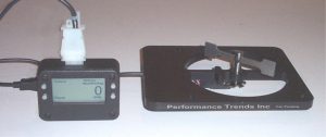
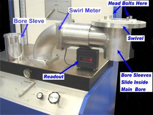
4) What happens to the mixture once the air enters the chamber? These measurements are called Swirl and Tumble measurements. Swirl is typically measured on 2 valve heads and Tumble on 4 valve heads.
Again, every head porter has their own theories on what works on their particular heads. However, on race motors it is clear you do NOT go for maximum swirl or tumble. At high RPM there is so much motion due to
squish and piston motion, that added motion tends to throw the fuel out on the walls. Some engine builders will actually design for the minimum swirl.