
Data Acquisition for an
Inertia Dyno
We've got the dyno built now, but how does it actually work??
Now we'll work on collecting data.........
Data Acquisition for an
Inertia Dyno
Data Collection
Probably the #1 stumbling block for most people looking to build a dyno of any kind is collecting the data. "Pump" dynos use either a gauge on the output to measure pressure or some method of measuring the "twist" applied to the pump body, seems easy, just write down or remember the gauge reading, but it doesn't usually work out quite right. With an inertia dyno the theory is to measure the time required to accelerate the load (flywheel), less time is more power. Technically you could do this with a stopwatch but the accuracy wouldn't be real good. In the case of our dyno, the time difference between 7HP and 10 HP is only 1 second. Most times I am looking for a .1-.2 gain, how do you do that accurately with a stopwatch? Even if you could, you still wouldn't be able to tell where the peaks in the powerband are located.
It quickly becomes obvious that this is a job for a computer. Well, that's all fine and good but how? Some sort of interface is needed to collect the analog data (engine rpm and flywheel rpm) and convert it into digital data that the computer will understand. Also some sort of software is needed to interpret the data and calculate the desired outputs. The "real" money around here comes from a job as an electronics technician, but even at that, this was going to be a big project. Lots of the calculations were done, some circuitry was even drawn up, but then we realized that the commonly available ports into the back of a PC weren't fast enough to collect the data at the rate we desired. Regardless of processor speed, common I/O ports aren't up to the job. This was going to involve a dedicated I/O board, which is available, but we still didn't have the software. ARRRGH!!!! At this point the dyno frame was built, complete with flywheel, etc, and we had done some running tests, everything was working, but we had no way to measure it. Something had to be done and soon. Many phone calls and internet searches were done without much success, some stuff was found, but either the price was beyond our means, or the software just didn't do what we wanted.
Finally we ran across a webpage for the Datamite Data Logger by Performance Trends. Immediately some of their products were recognized as the same ones sold by places such as Jegs Performance, Summit Racing, and Steve Smith Autosports.
Performance Trends writes some of the most well known and well respected Engine Analyzer and Drag Race Analysis/simulator programs in the industry. They had been known about for years, and now realized they had a data collection system also. Could it work for an inertia dyno? Maybe! After downloading the demo programs / product brochure and looked them over, everything looked like a possibility. The Datamite system is actually intended to be an "on board" data collection system. Sensors are connected for engine rpm, wheel rpm, etc. The data is collected in memory and then downloaded to a computer. What if you "lied" to it and made it think that the dyno was a vehicle? Sounds good, maybe it would work. We knew of at least one other dyno available that was doing the same thing. After looking at the demo for the software used on that system, we had not been impressed. The Datamite program however would supply all the info we wanted and more!
I called Performance Trends and talked to Kevin Gertgen, "can this actually
work??"
He was interested in the project, and seemed to think it would work.
A Datamite system was ordered.
One note: I have to stop here and thank Kevin Gertgen at Performance
Trends. Kevin has been very patient, extremely helpful and great to work
with on this project. He has made several "free of charge" updates to the
software to make the dyno more accurate and easy to use. If you are interested,
call or E-mail Kevin.
The Datamite system:
At this point in order to get a full understanding of the process we
recommend you go to the Performance
Trends website at www.PerformanceTrends.com, look over the Dyno
Datamite section pay attention to the system requirements, and then
go to the "downloads" page and get the Datamite
DEMO software. The DEMO software includes example files to use, and
excellent "on screen" help.
The standard Datamite records up to 4 input channels at once including, engine rpm, flywheel rpm, CHT, EGT, oxygen sensors, pressure transducers, airflow meters etc.
The Dyno Datamite system even has the ability (with options) to automatically
collect the weather conditions from a seperate weather station. This information
is VERY important for comprehensive dyno testing. the weather numbers can
be manually
entered also.
The standard Datamite system (DTM128) includes: recording module (4 channels, 128k memory), control panel with 2 pushbuttons, serial downloading cable, fully wired harness with leads for tach pickup and flywheel sensors, 4 magnets for RPM sensors, Datamite Dyno software, and Excellent user's manual.
Options needed with Datamite:
Inductive pickup for single cylinder engines (DTM-IPU), and 120v AC
adapter (DTM-PS)
Approx. cost at this writing: (Feb. 2001)
Datamite system (DTM128) $559
Inductive Pickup (DTM_IPU) $ 45
Ac Adapter (DTM-PS) $ 25
Total $629
This is the base system that will give you pickups for engine and flywheel
rpm. Many, many options are available
The only other item needed (besides the dyno itself) is a cheap, cast-off computer system. Bigger is better, but only marginally. Currently we use a Pentium 90 laptop, not lightening fast, but adequate. Any machine capable of running Win95/98 is perfectly adequate. A color printer is a nice addition, it's not neccesary, but with color printers now under $100 why not??
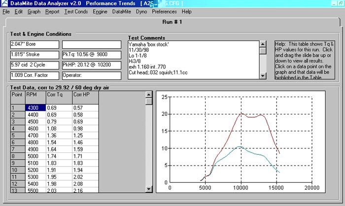
Main Screen
This is the main screen that you see while running the
Datamite Dyno software.
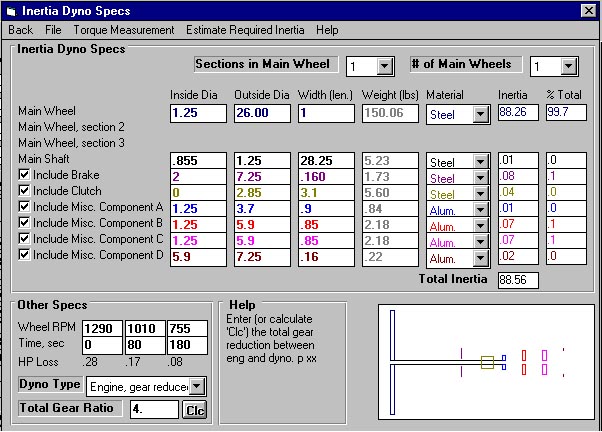
Dyno Specs Screen
This is the screen that you use to input the size and material specs
of all the components on the main dyno shaft.
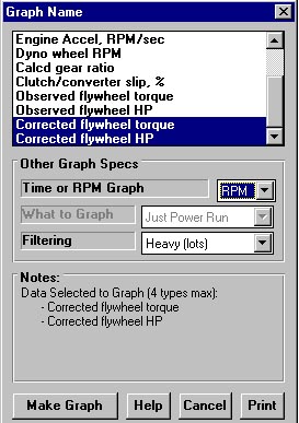
Graph Selection Screen
This is the screen that you use to select the type of graph that you
wish to create.
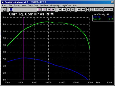
Typical Graph.............
Many graphing options are available.Any recorded info can be graphed
against time or rpm
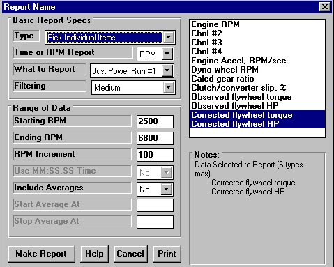
Report Selection Screen
This is the screen that you use to select the type of text report that
you wish to display,
as well as the parameters of the report.
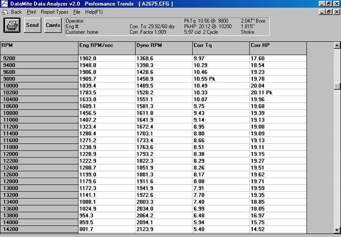
Typical report.........
Again,many options are available,any recorded info can be displayed,along
with averages.
All screens are printable
Datamite Specs Screen
This screen is used to set up the type of Datamite used and the data
recorded on each channel

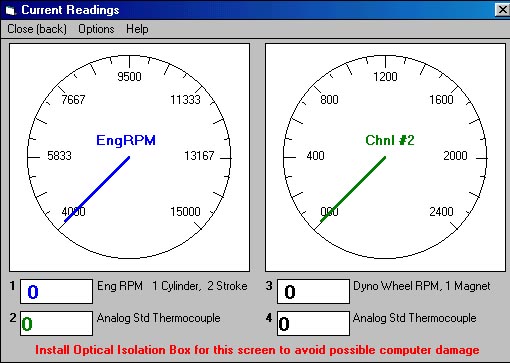
Live On-Screen Tach/Temp Displays
Each of the 4 datamite channels can be monitored live on-screen while
recording.
Now you should have all the parts and equipment needed for the dyno
project. The following pages will explain how to make it all work together.