
Mechanical Components of an
Inertia Dyno
Finally we can begin to talk about the components of the Inertia Dyno
This system can and is entirely safe if do correctly, but there are
some things to watch for,
Please read the following carefully........
Flywheel
Warning!!!!! Due
to the size/weight of the flywheel needed, and the speed that it needs
to turn, EXTREME care must be taken in its construction. Failure to do
so can and will result in major damage to you, your property and the property
of others, personal injury and possibly death!!
This is entirely up to you, if you do not feel comfortable at this
point, turn back now. Neither TDKMotorsports nor any of our associates
will be held liable for damages caused by the use of the following information.
WARNING WARNING WARNING WARNING
WARNING WARNING
Please use some common sense in
the construction of a dyno, your life will depend on it!!
(The following is an example of what not to do.)
Recently...
It has come to our attention that someone has built dyno using a flywheel
made from railroad car wheels. This in itself is not all wrong, assuming
of course they are properly balanced etc.
However, connecting them to an engine in a direct drive configuration
and spinning them to 6000 rpm!!!!! is NOT a good design.
Remember the laws of physics still apply and
at this RPM there is a very real chance of the flywheel becoming a bomb
by exploding due to centrifugal force. Please see the warning below for
more information.
Please use a bit of common sense and if you
have ANY doubts as to the suitability of your design PLEASE contact us
first.
WARNING WARNING WARNING WARNING
WARNING WARNING
This is serious business, the flywheel you need is going
to be approx. 2 ft+ in diameter, 1" thick and weighs 135lbs+, spinning
at 2000 rpm or more. If it should fail in any way, it can and will cause
serious damage! This can be done safely, however if you try to use some
egg shaped piece of steel, strap it to an axle, and spin it 5000 rpm ...
The authorities may never find you or it again! Please use some common
sense, the construction of this flywheel is best farmed out to someone
who can do it right. (call in all the favors from buddies who may be in,
or have contacts in the machinist business) It must be perfectly round
and balanced, it must have a center hub securely welded in, and keyed to
the axle. Do not attempt to balance the flywheel by drilling holes in
it, this only balances it for a given RPM and will also weaken it which
increases your chance for disaster. You must build the frame of the
dyno to include some integral scatter shield in case for some reason there
should be a failure. Remember that you may need to allow for removal of
the flywheel for service at a later date. The flywheel is probably the
one reason, other than the data acquisition system, that people don't build
their own dyno, it can be a little intimidating.
Again, this can be done safely, you just have to be careful.
Here are some of the considerations you need to be aware of:
Size/weight:
We've done some of the work for you here, the wheel that we are using
is 24.5" in diameter 1" thick, weight is approx. 135lbs, made from plain
old hot-rolled steel plate. We got lucky and came across a couple of steel
disks in the scrap yard that were about the right size. We did all the
rest ourselves, cut the center hole, welded in the center hubs with 1.25"
keyed holes, and then spent many hours trying to make it round and balanced.
We wouldn't recommend it to anyone to do, in fact we would pay someone
to do the next one, it was far too much work, and we nearly messed it up
a couple of times. Not having the proper tools to do this it really wasn't
worth the hassle.
Checking some local prices:
Steel: 26" diameter x 1" approx. $85
Weld in center hub and machine round approx. $300
This was quoted from a local shop that is known for being pricey, if
you do some checking you should be able to do better, even at these prices,
doing it yourself really isn't an option for most people. Again, call in
the favors.
(See the FAQ
page for what size wheel you should use for your dyno)
WARNING!!!! It
is possible to spin a piece of plate steel fast enough to for it to burst.
The centrifugal force becomes so high that it exceeds the tensile strength
of the steel and it explodes. BOOM!!! You're dead!! Not a nice thought
but, this is one of the dangers you should be aware of. We have had the
calculations done. We won't tell you what the actual numbers are. However
spinning a 30" wheel to 2000rpm, or a 24-25" wheel spinning up to 3000rpm,
should allow you all the capacity you'll ever need for 20-25 HP, and still
be well within safe limits, again assuming the wheel is perfectly round
and balanced! Choosing a large enough wheel to give you acceleration
times in the 8-12 sec. range is about right.
Safe operation is the responsibility
of the operator/builder. TDKMotorsports will not be held liable for any
damages caused by the use of this information.
More Size/weight:
If you really need to know more than the guidelines given above, here
are the relevant formulas...
The formula for determining the torque is:
Torque = PM * rpm per second / 9.551
where "PM" represents the Polar Moment of Inertia of our inertia dyno's
flywheel.
If you don't know the Polar moment of Inertia for the flywheel (and
your flywheel has a constant thickness cross-section) we can calculate
it with the formula:
PM = (W * r^2) / 32.16 / 2
where "W" represents the flywheel weight in pounds and
r is its radius in feet.
(the formula for weight of a steel disk can be found in the "FAQ" page)
Once you have the torque, it is easy to calculate the horsepower with
the standard formula:
Hp = Torque * rpm / 5252
Keep in mind that the rpm in the last formula must be the average rpm
during the sampling period.
Say our example uses a 10 pound flywheel, 8" in diameter (thus it would
have a Polar Moment of Inertia of .017 foot-pounds-second^2). If the engine
was able to accelerate this flywheel from say 4,800 rpm to 5,200 rpm in
2/10 of a second (a rate of 2,000 rpm per second) that would represent
a torque of 3.6 pound feet. Since our above example had an average rpm
of 5,000, it produced 3.4 Hp during the test.
If you have any questions about using this formula feel free to
contact: TDKMotorsports
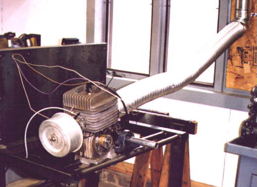
Finally some pictures of what we've been talking about........

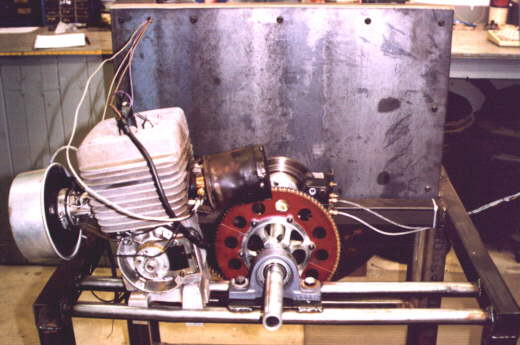
Pictures showing heavy duty scatter shield to contain any disasters,
which might occur.
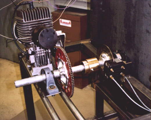
Frame
Here is one place where a picture is worth a thousand words, or absolutely
nothing. The pictures will give you a general idea, but the actual configuration
is up to you.
Here are a few considerations:
1. Make it sturdy, weld all joints. 2" x 2" x .095 works great.
Single cylinder engines produce an amazing amount of vibration, you don't
want it to shake apart.
2. Build the frame in such a way that it will allow easy access
to the motor.
3. Make everything as close to a regular kart configuration as
possible, this makes it easier to take the motor off the kart and mount
it on the dyno.
4. Put some rubber castors on the bottom so it can be easily
parked in the corner when your not using it, also helps to absorb some
of the vibrations.
Axle assembly
Use standard kart pieces here as much as possible, makes it easy to
integrate everything together. Otherwise nothing fancy.1.25" kart axle,
sprocket hubs, brake rotor, etc. The only exception is using cast iron
pillow block bearings, just because they were easy to bolt down to the
frame. You may want to get an extra sprocket hub to make it easier to swap
between motor types.
The portion of the axle that goes through the flywheel and flywheel
bearings is recommended to be solid.
Brakes
Kart type brakes are normally sufficient unless you intend to pull the
motor against the brake in an attempt to build heat. If that is the case
you may want ventilated or dual rotors. Slowing the flywheel is the only
other purpose here. Listening to the flywheel spin itself down gets really
irritating! We once let it do this by itself, would you believe it spun
for 8 minutes and hadn't stopped yet! Attempting to stop the flywheel too
quickly with a large brake can cause the entire dyno to try to tip over.
Remember though, all these components contribute to the "inertia weight"
which can mess with the accuracy, especially if you change something mid-stream.
One-way clutch
THIS IS VERY IMPORTANT!! After the
flywheel/engine has been accelerated and the throttle is closed the flywheel
will want to continue to rotate at high rpm and decelerate very slowly
(see above), while the engine will attempt to slow much quicker. When this
happens the engine becomes the brake for the flywheel. This "engine braking"
is very hard on your engine, the vacuum caused by the throttle being closed
places the connecting rod and piston in "tension", they are being "pulled"
instead of "pushed", exactly the opposite of what they were designed for.
Stresses on these parts can be as much as 200-500% higher than normal during
this "engine braking" period. Also remember 2-cycle engines are getting
no oil when the throttle is closed. A brake on the flywheel is not fast
enough. A centrifugal engine clutch doesn't work very well here either,
remember the flywheel is doing the driving, all the pieces in the clutch
stay locked as long as they are all spinning at the same speed. (until
the clutch assembly slows to below stall speed) You can try it without
if you want, but it's not a pretty deal. We did alot of searching here,
several options were looked at. There are available, some one-way bearings
that would work great for this, just like the ones in an electric starter
drive. The problem is, by the time you get a bearing that will handle the
torque load and abuse of a single cylinder engines alternating power output
(one of the most harsh things you can do according to the "power drive"
industry, they step up the size of components by about 30%+ if they are
used on a single cylinder engine) you get into some expensive pieces. We
found one piece that would have worked great, it had an 11/4" keyed hub
inside and a "bolt on" flange for sprockets on both sides, really cool!
The price was nearly $500! Not an option as far as we were concerned! We've
been told that a kart style axle clutch would work here, but haven't gotten
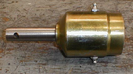
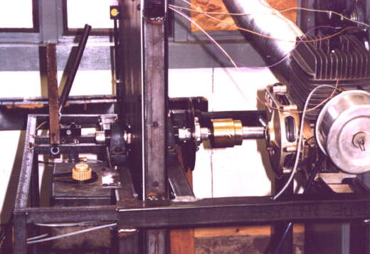
hold of one to try. Looking at the pictures, you'll see a small gold colored
deal between the sprocket hub and the brake rotor. This is our solution.
It's an adapted piece of farm equipment. (Hey, we're farm boys!) It has
some limitations, but it was cheap! It needed a small amount of machine
work first but works great.
Info added by Performance Trends, Nov 2,
2017: Check the last page (FAQ page) for this TDK website more info on the
one-way clutch.
Picture of one-way clutch after machining........
Update Sept-2004:
These clutches are very simple but have proven very reliable. Many
dyno builders are reporting literally thousands
of runs with no failures.
I can make one of these clutches for anyone who cannot find one
or cannot get the machining done themselves.
They are done on a "made to order" basis to fit your specific application
however.
Price is $140 including shipping.(Must be pre-paid)
Picture showing one-way Clutch, Brakes, and axle assembly
Engine Clutch
An engine clutch is used simply for ease of starting etc. Direct drive
was attempted, but just didn't work out real well. The engines were hard
to get started because we were trying to "start" the flywheel at the same
time, the engine would start and have to accelerate the flywheel while
trying to get to an idle. Putting a clutch on works much better. The only
thing you have to do is set up a clutch for very low engagement in order
to be able to accelerate the motor through the entire power band, before
and after the torque peak. A Yamaha clutch set to stall at approx. 6000rpm,
and a Briggs clutch at approx.2000rpm are used now and work quite well.
Now the engine can be started, warmed up, etc. When doing a "run" the engine
is brought up to the clutch rpm, the flywheel is allowed to catch up so
everything is locked together, then the throttle is opened form there.
Gauge
The data acquisition system is capable of recording and displaying CHT
and EGT "live" depending on the configuration(optional hardware),however
if you do not have this capability you'll need something.
We use a Digatron off of a kart to monitor these in real time. You
can use one from your kart or used ones can be had a swap meet very reasonable.
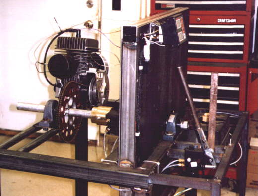
That should about do it for the pieces-parts explanation, take a look
at the pictures for ideas on throttle controls, fuel tanks, etc.
Sorry the dyno isn't real pretty. Since we got it all working, we've
been USING it, and haven't had time to tidy it up much.
Update Sept 2004
Unfortunately (or fortunately, depends on your point of
view) my dyno still looks like this today.
I didn't build it real pretty originally because I wasn't really sure
it was going to work...........
Now, it works so well I haven't had any reason to take it apart and
"pretty" it up. NOTHING has been changed on it since it was built.
More pictures
Back
HomeNext
Contact us at: TDKMotorsports
This is an informational site about
the construction of a prototype Inertia dyno. Large metal objects spinning
at high speeds are very dangerous and may cause severe injury or death.
TDKMotorsports will not be held responsible for any damages to you or your
property due to your use of the information provided on this site. By using
this information you assume all responsibility for any loss or damages
incurred.