
Final Notes/List of Materials/FAQ's
Inertia Dyno
Some final thoughts,and some of the most frequently asked questions..........
Final Notes/List of Materials/FAQ's
Inertia Dyno
Was it all worth it?
YES!!! In every way.
Why are we sharing it?
Originally this project was intended for our own use, however after getting it up and running it worked so well that we thought that it was only right that we share it with everyone,hence the birth of this webpage, our "contribution" to the sport of kart racing.
There have now been over 75000 visitors to this website,and the number of dyno's built is well past 200 across the country and around the world.
Very little approaches the satifaction that I get when I recieve
an E-mail or phone call from someone who has made their first
successful dyno runs. As of yet I have not heard from anyone who has
been dis-satisfied,I only hear from those that are thoroughly enthused
and excited. Many users claim very good successes in both their engine
building and racing as a result of building this project. Nothing in this
price range can compare.
HAVE FUN!!!.......
If you have any questions/answers/contributions/complaints please E-mail
us and let us know, we are here to help.
We have received a multitude of questions about our inertia dyno. Most of these questions involve the use of different types of flywheels, brakes, gearing, clutches, etc. Keep in mind that there are many different/better methods for doing something, however these are the methods we used. Many of the parts we used were selected based on what we had on hand or were readily available, most of which were kart parts. Assuming that most of us have some extras lying around, why not use them? Here are some of the questions we have received and some answers to them:
Just how accurate is this dyno?
"Accuracy", for many reasons, some of them mentioned in this website, is a very relative term as far as dyno's go. Just how accurate is anyone's dyno? Take 2 motors, test them on 2 different dynos, one comes out at 8hp, the other comes out to 9hp, but they run the same lap times. Which dyno is "accurate"? Which one is giving you the correct numbers? Horsepower is simply a calculated number. Dyno 10 engines on the same dyno at 8HP, put them all on the same kart one at a time, and they all run the exact same lap times. Is the dyno accurate? No, the dyno is however "repeatable". "Repeatability" is what you want in a dyno, test the same engine time after time and get the same results. Take one of the 10 engines from above, change a pipe or a cam so you get 5% more power, run it against all the others again. It runs 5% faster, you redyno it and it still says 5% better, now you have an "accurate" and more importantly, a "repeatable" dyno. If you follow the advice in these pages you will have a system that is every bit as accurate as you will ever need. A couple hints: Always start your tests at the same engine temps and settings. Pay close attention to weather conditions. Get yourself a good barometer, thermometer, and humidity gauge, and enter the conditions into the program each time you make a run.
The Datamite only records at 60hz (60 readings per second). Shouldn't it be more than that??
No,not really,for a couple reasons.......
1. The faster you collect data,the faster
your hardware(computer) has to be,and the more likely you are to have problems.
The hardware needed to collect data at
500-1000 samples per second would quickly send the price into the $15-20,000
range,and would actually be more prone
to electrical noise and breakdowns.
The Datamite system is very immune to electrical
noise,and very rugged,especially when you compare the price.
2. Other systems may actually collect more
data,but very little of it ever actually makes it to the screen as a graph.
Many of the software programs do not actually
look at all the data that is collected,and what is used has been through
so much averaging and filtering that you never
see most of it anyway.
Remember,in a dyno situation you rarely look at individual data points. What you are looking for is the shape of the curve,which is the average of all the data taken anyway. Having more data rarely does alot of good here.
Plain and simple,the Datamite is hard to beat.
What size flywheel should I use?
This
one place where bigger is not neccesarily better. Problem #1 is getting
a wheel made. As you go up in diameter,the availability of equipment to
machine the wheel gets smaller and harder to find.There are alot of lathes
around that will handle a 24" wheel,but very few that will handle a 30"
wheel.
The wheel on our dyno is 24.5" in diameter
which is more than big enough to handle most any kart engine with the possible
exception of some of the "open" motors. If you plan on running these motors
go with a bigger wheel,probably in the area of 26-28 inches.
What gear ratio should I use between the engine and axle??
The best advice
here is to use the gearing that gets you closest to the amount of "run"
time you want. Your looking for total acceleration times in the area of
8-12 seconds.
A 4 to 1 gear ratio works very well for most
Briggs motors with a 24" flywheel,and a 6.5 to 1 works well for most 2-strokes
using the same wheel. If you go to a larger wheel you will put more load
on the motor,which means you have to g to a higher gear ratio. (5-6 to
1) this will slow the wheel down and shorten the run times.
Can an automotive/diesel truck/tractor or other type of flywheel be used?
Yes, you could use most anything for a flywheel, however there are a few items that need to be taken into consideration...
The flywheel must be heavy enough and spun fast enough to produce acceleration times long enough to collect reasonable data, yet not so long as to induce unneeded stress on the engine. Acceleration times in the 8-12 second range seem to work very well. Changing the gearing to spin the wheel faster or slower will raise or lower the load on the engine and influence the acceleration time. Diameter is actually much more important than the weight of the wheel. With a larger diameter the weight is farther from the center of the circle, making it a larger "lever", which will be harder to turn. Take a look again at the basic formula for inertia of a flat disc:
"I" = Inertia
I=1/2MR^2 Where: I=inertia M=weight of the wheel in pounds divided by 32.2(the constant for gravity) Weight= volume of wheel in cubic inches (radius squared x pi x thickness) x .2833(weight of steel/cubic inch) R^2= radius squared
In this formula, the diameter is the multiplier and holds the biggest deciding factor. If you pick a couple of numbers and run through this formula, you will see that changes in diameter add up quickly. Example: Our wheel measures 24.5" in diameter x 1" thick, approx. weight = 133lbs Running through the formula you'll find that "I" equals approx.310
Now, try a wheel 18" in diameter... With a little backwards math, you'll find that in order to get the same weight in lbs. the wheel will have to be approx. 1-7/8" thick. If you can handle this then run the numbers through the formula again and you will find that the "I" of this wheel is only 168! What this means is that you'll have to spin the wheel nearly twice as fast to achieve the same loading on the engine.
Try the other direction... 30" wheel 1/2" thick Approx. weight only 100lbs Approx. "I"= 349. Now you can actually spin the wheel slower with the same results.
Once you start thinking about this, something like a flywheel from a car quickly becomes less attractive for a couple reasons...
1. Weight/diameter-most car flywheels are only 12-15" in diameter and approx. 1" thick. Most weigh less than 50lbs. You'll have to spin these really fast to get much of a load on the engine, this requires a major gearing change, which means you'll have to go out and buy several sprockets/chains etc instead of using a larger wheel which allows you to use standard kart parts.
2. Be careful with automotive flywheels (and some others for that matter), some of them are not "neutral" balanced. Many manufacturers use flywheel/balancer combinations that are counter-weighted to help balance the internal assemblies. A Chevy 400 is one example, most Fords also are "externally" balanced. Ford had 2 systems, one used 50oz.of weight, the other used 28.5. Spinning up a flywheel with 2-3 lbs. of counterweight could be really exciting!
3. Most automotive/truck/tractor flywheels are made of cast iron, assuming you'll be rummaging through someone's junk pile to find a flywheel, be careful, there is usually a reason something is in the junk pile. You don't know for sure what is wrong with it. Having seen the damage caused by an exploding cast iron flywheel, I can tell you that, you don't want it to happen to you!
How do I calculate the weight of the flywheel??
The
formula looks/works like this:
Pi x R^2 x thickness x weight of steel/cubic
inch
Or
Pi(3.14) x wheel radius inches squared
= area of round wheel in square inches
x thickness of the wheel in inches
= volume in cubic inches
x .2833(weight of steel(lbs) per
cubic inch) = weight in pounds
What kind of hub do you use to attach the flywheel to the axle?
The flywheel hubs are also a piece of farm equipment.
They are designed to have a sprocket welded to them to create a gear for
use on farm equipment. Just weld them to the flywheel. Here is a picture
of them as purchased.
These hubs are manufactured by G&G Manufacturing as part of their
"Weldasprocket"
line. Webiste here: http://www.ggmfg.com/product_subcategories.asp?cat=weldahubs
You are looking for their "XX" series hubs which are the largest outside
diameter.
Most bearing supply houses and farm-fleet type stores carry G&G
products
Can an automotive caliper be used directly on the flywheel for the brake?
Again, yes you can. Theoretically. But consider these points:
1. A flywheel weighing 130lbs spinning at 1500-2000 rpm is a lot of stored rotating energy. Our flywheel will spin for approx. 10 minutes if left to slow down on it's own. Considering the fact that the dyno frame/engine combination probably weighs less than 200lbs, you don't want to stop this kind of stored energy too quickly. It is entirely possible that if you clamped the caliper down on the wheel too quickly the entire frame could rotate around the wheel and land on your toes!
2. Some automotive calipers are not the easiest things to mount to a frame. Most have some goofy mounting system, plus most need to be made to "float" so that both brake pads will clamp evenly. Considering the ease with which a standard kart caliper mounts up, they are much easier to deal with.
3. Cost of a complete Paul Martin brake system including caliper, master cylinder, brake rotor, rotor hub and lines retails for $150-175, brand new. You could easily find all these components at a swap meet for far less than this, and still have matching components. By the time you round up a car caliper and a suitable master cylinder, then figure out how to mount and plumb it, the kart components become much more attractive.
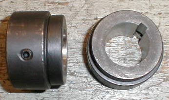
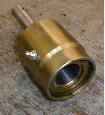
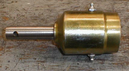
What is the one-way clutch that is being used?
As we said, the one-way clutch is actually an adapted farm equipment piece, commonly called an over-running PTO clutch. They have been used for years on older farm tractors without "live" power take off systems. The clutch was used with "high inertia" implements such as brush mowers or balers that continued to spin after the power was removed, which without the over-running clutch would continue to drive the tractor forward even with the engine clutch disengaged, quite an exciting and dangerous ride if you are not prepared for it! These clutches should be available at most farm-fleet or bearing supply houses for approx.$60-80. Basically they look like a male-female coupler with a large ratchet inside, most have a six spline male end approx. 1-1/8" outside diameter and a corresponding same size female end. What you will need to do is to machine the splines out of the female end, large enough to slip-fit over the axle being used, and machine the male end to fit the inside of the kart axle. The only real tricky part here is that the splines inside the female end are VERY hard and a bit difficult to machine, however most any reasonably equipped machine shop should be able to make quick work of it. The clutch is designed to be "roll" pinned to a shaft which is what we did and it seems to work fine. Here are a couple pictures to show what it looks like after it has been modified for dyno use.
Info added by Performance Trends Aug 17, 2017: The clutch comes apart by removing the snap ring. Slide the inner portion out but be aware there are some springs which may pop out as you do this. Now you can machine the inner portion and determine how to attach it (female portion) to the shaft. You could do it with a roll pin or set screws. Then slide inner portion back over outer portion with springs and other components in place.
Are there any plans/drawings/parts lists available?
For a couple years I promised to have drwaings
and plans available for this project, however the more
I thought about it the more I had reservations.
The mechanical portions of this project are relatively
simple for most anyone that has any basic mechanical
knowledge.
Quite frankly, if a person cannot figure out
the majority of it on their own I have to question their
ability to do a safe job of building, and also
have to wonder just how much use they will get out of it.
That said, if you have a question about something
that you just cannot figure out please feel free
to contact me.
Can something other than the Performance Trends Dtamite software be used to collect the data?
Yes, you can use whatever data aquisition system
you can come up with.
Remember that your final results are highly dependant
on your abilities to manipulate the data.
Also, if have any intentions of marketing your
engines or your dyno services, you need to be able to present
your customers with clear and concise data tha
they can understand, and in a format that if nothing else looks
impressive.
A quote on the virtues of the Datamite system
from George Clausen of Clausen Racing Engines, Bettendorf Iowa:
"I have used/owned many of the data aquisition
systems on the market, comparing most of them to the
Performance Trends Datamite system is like comparing
Pong to PlayStation"
Says it all....................
Is the inertia dyno something you can drive/ride on?
NO
Has anyone built one of these dynos from the information provided on this site?
Yes! Go here to see what others have done with the information on this site. (Several pictures please be patient)
So what if I don't want to build a dyno,can I get my engine dyno'd???
Absolutely....TDKMotorsports can dyno your
engine for you at a very reasonable cost,and give you all the info you
see here.
Simply E-mail us at TDKMotorsports
If you have built a dyno or are in the process we want to hear from
you to: Please E-mail TDKMotorsports