Performance Trends, Inc.
Producing Quality Computer Tools for Racers and Engine Builders since 1986
Shock Dyno
Complete Shock Absorber Tester/Dyno System, or Computer Program and Electronics as Retrofit Kit
for Windows XP, Vista, Windows 7, Windows 8, Windows 10, Windows 11

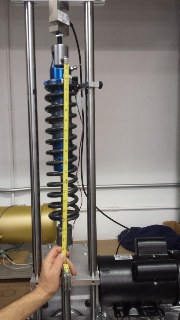
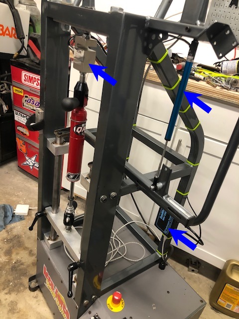
Shock dyno showing wide mast spacing (7.5" between masts) and infra-red temperature sensor with flex mount.
![]() for pictures showing how powerful our shock dyno is.
for pictures showing how powerful our shock dyno is.
![]() for details of the new V1.1 C software starting on page 73, released May 2018.
for details of the new V1.1 C software starting on page 73, released May 2018.
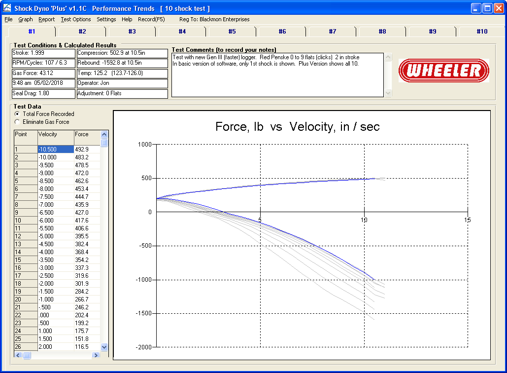
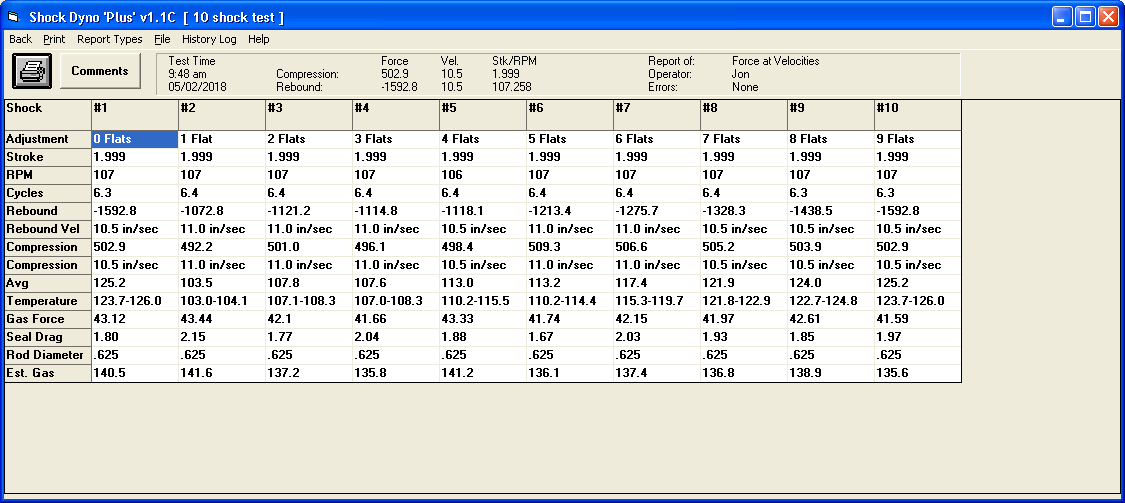
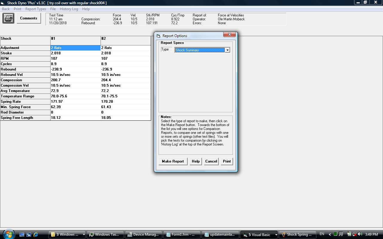
New v1.1C Main Screen for Plus Version, lets you combine up to 10 shocks into 1 test file
Our Complete Shock Dyno features include:
- 2.0 HP, 110 VAC motor (ideal for most trailers and generators). 220 VAC 2.0 HP option available.
- Stroke is adjustable for 1 and 2 inch strokes.
- Up to 14 inch/second shock velocity.
- 2000 lb load cell.
- With standard 36 inch masts and 2 inch stroke and the load cell adjusted to maximum height, the eye to eye distance of the shock will cycle between 23 inches to 25 inches. Obviously you can lower the load cell to any distance less than that. Mast extensions are available to accommodate longer shocks.
- Can handle forces over 1500 lbs and more.
- Optional shock temperature sensor, and warm up procedure before testing.
- Optional Plus version of Shock Dyno software with several advanced features.
- USB computer interface.
- English (inches, inches/second, and lbs) or Metric (mm, mm/second, KG or Newtons) units.
- Safety Shutdown if Max Force is exceeded.
- Software compatible with Win XP, Vista, Win 7, Win 8, Win 10, Win 11. See features listed on this page.
We also offer the sensors, electronics and software as a "retro-fit" kit for your existing shock dyno, described at bottom of this page.
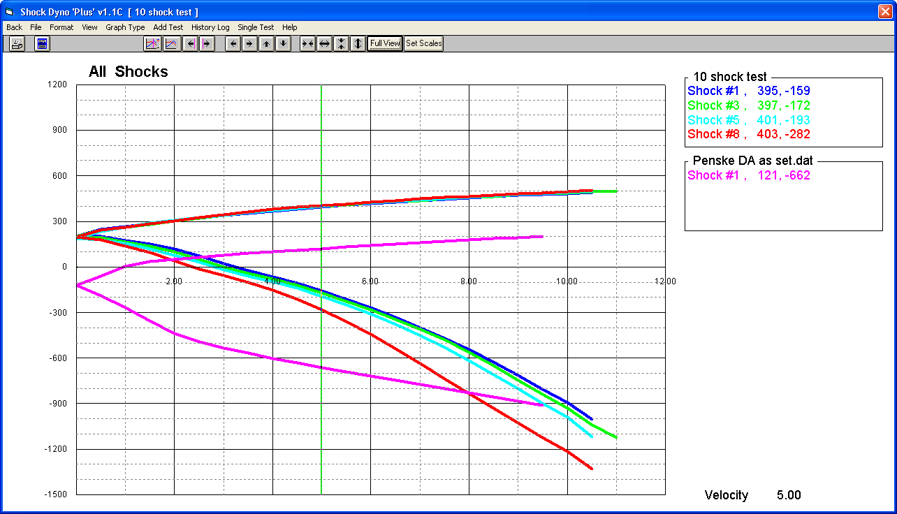
Overlay Graph of 4 Shocks from 1 file (selected from file containing 10 shocks) and 1 Shock from a different file. Green cursor Pin-Points values at both compression and rebound.
Overview:
The Shock Dyno Retrofit Kit provides a load cell and length sensor, plus electronics to record both channels. Once data is recorded, you can create reports or graphs of the results. You can also overlay graphs from several different shocks for comparison.
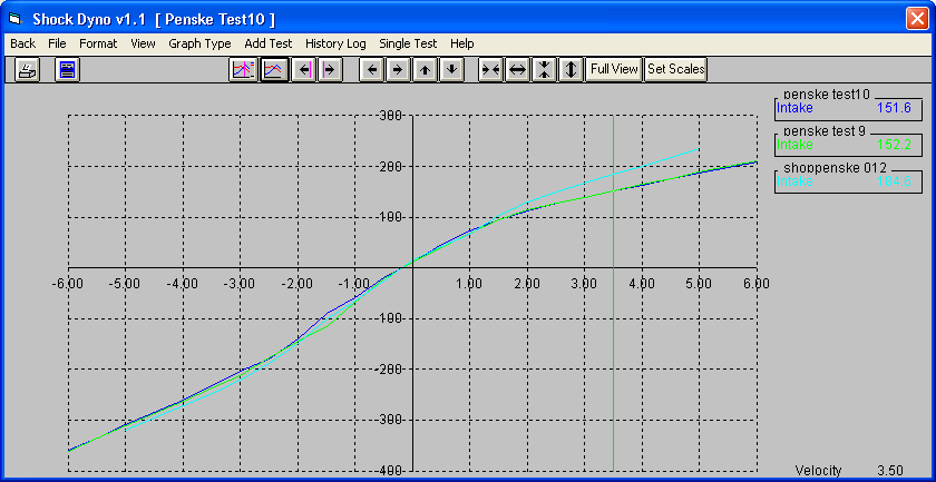
Graph with just + Velocity
Options:
The program has several options, including:
-
You can graph results either absolute velocity (typical of most shock dyno programs) or versus velocity with direction. This 2nd choice lets you pin point differences on the graph more easily with the cursor.
-
Modern USB electronics for easy installation on newer computers.
Overlay plots for comparison.
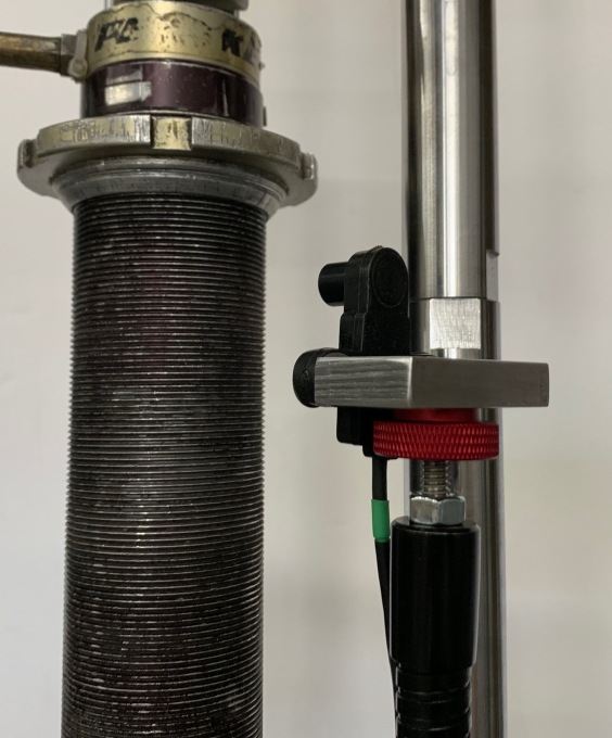
Infra-red (non-contact) temperature sensor (optional with Plus software).
Start testing immediately or when a user selectable temperature is reached (temperature requires Plus software).
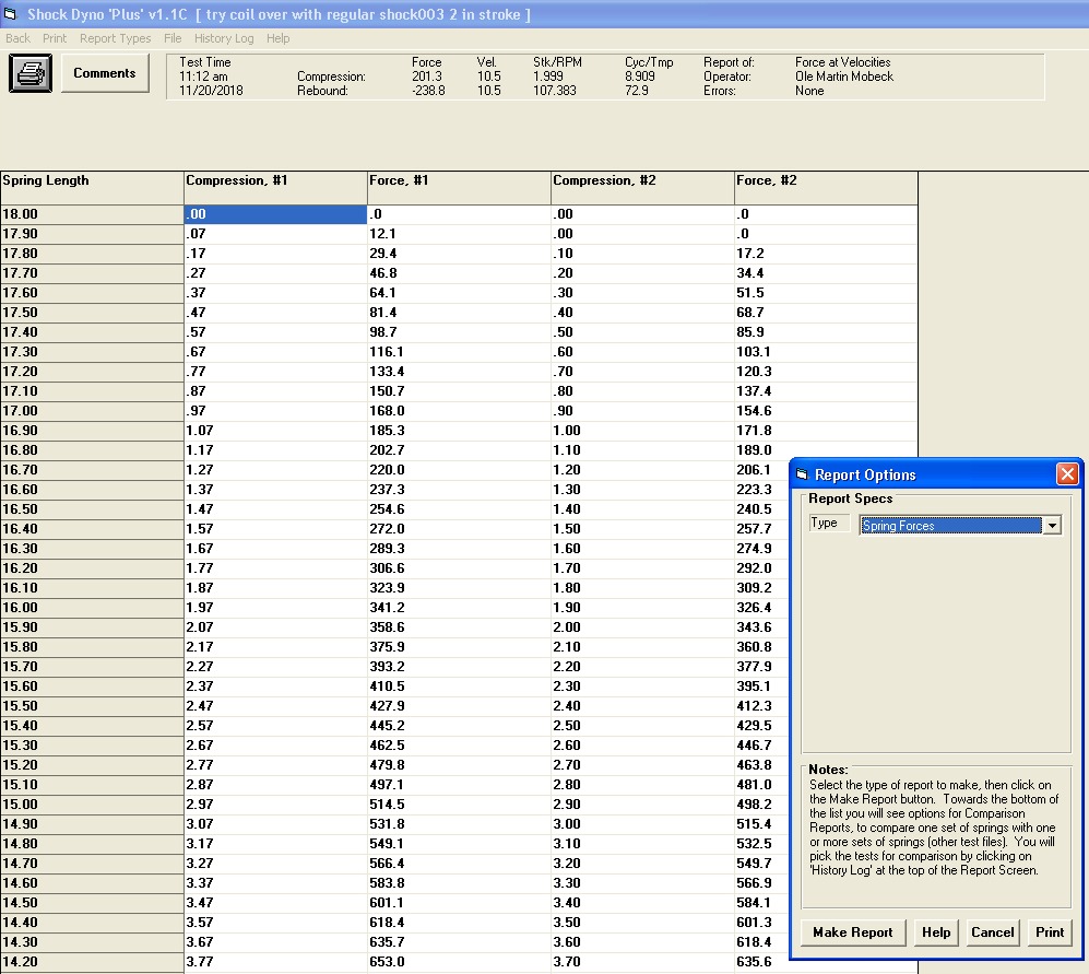
Summary of results as shown below, for max Compression and Rebound force, Stroke, RPM, Test Cycles, Average/Max/Min temperature, etc.
Programmed or user selected test time.
Over-Force shutdown safety. If the system detects a force greater than user selectable limit, the motor is turned off. This can happen if you install the shock incorrectly.
Dimensions:
- 24 x 16 inches x 12 inches high.
- 165 lbs
- 7.5" spacing between the masts
- Standard "masts" extend 36 inches above dyno enclosure. With standard 36 inch masts and 2.5 inch stroke, the eye to eye of the shock will cycle between 22.75 inches to 25.25 inches. At 2" stroke it will cycle from 23 to 25 inches, at 1" stroke it will cycle from 23.5 to 24.5. Obviously you can lower the load cell bracket and shrink all these lengths down to zero.
- Mast extensions available to accommodate longer shocks, typically in 12 inch increments.
The software provides for an optional Plus version, which adds several features:
- Allows for temperature input, and for triggering recording to start at a particular, user selectable temperature. This provides for better test repeatability.
- Additional graph types including:
- Force vs Velocity Loops (which will show hysteresis in the shock, very useful for troubleshooting problems in the shock)
- Force vs Position (sometimes called "football graph") See picture below.
- Velocity vs Time (good for troubleshooting system)
- Force vs Time (good for troubleshooting system)
- Position vs Time (good for troubleshooting system)
- Position vs Time - Raw (good for troubleshooting system)
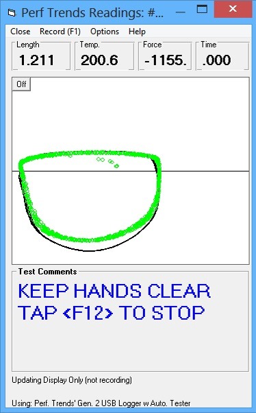
- "Real Time Graphing" prior to recording, so you can spot that the results will be what you expect. See picture below.
- Company Logo appears on main screen also, in addition to printouts.
- Combine up to 10 shocks in one test file. Updated version 1.1 C only.
- Allows for naming each shock as a number 1-10, R Front-L Front-etc., or any custom names you want. Updated version 1.1 C only.
- Measure Gas Force and Seal Drag. Updated version 1.1 C only.
- Import certain versions of Roehrig (tm) .cvp files for comparisons, analysis, etc. Updated version 1.1 C only.
- If you change the Force Sensor calibration, the test file can be updated to reflect this change. Very handy for correcting mistakes or converting between force units of lbs, newtons or KG. Updated version 1.1 C only.
- Allows for input for each shock tested of "Adjustment", for number of clicks or most anything you want to record. This info is displayed on graphs and reports for each shock. Updated version 1.1 C only.
- Shock Summary Report, listing critical data for each shock in a test, like Adjustment, peak Compression and Rebound force, temperature, gas force, seal drag, etc. Updated version 1.1 C only.
- Calculate Gas Force based on gas pressure, temperatures and strut diameter. Updated version 1.1 C only.
- On Main Screen, there is an option for either displaying data as "Total Force Recorded" or "Eliminate Gas Force". Updated version 1.1 C only.
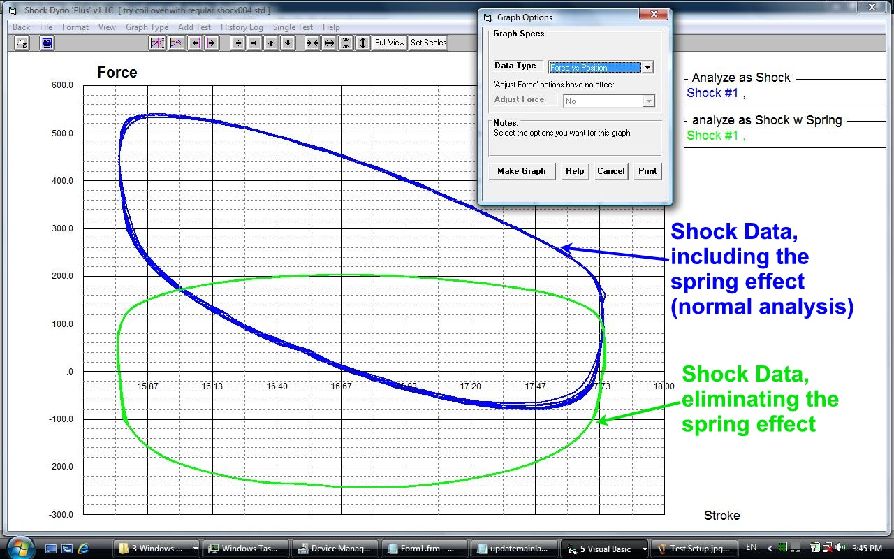
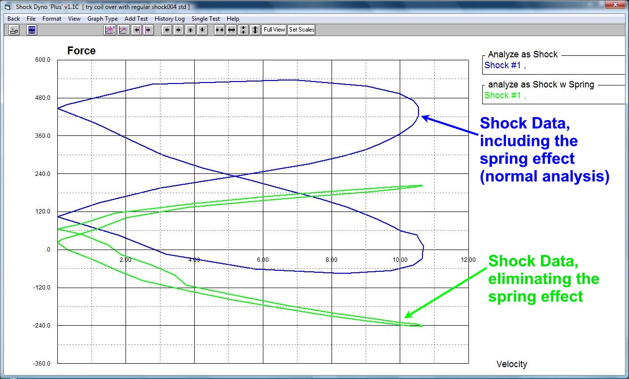
- Analyze data as "Shock w Spring" to more accurately measure Coilovers and motorcycle forks.
Real Time Graphing - Green dots are current readings, black lines are from
previous test
"Football" graph of Force vs Position for 2 different shocks

Shock Dyno Summary Report
"Shock w Spring" Analysis (Plus version only)
Typically when you test a shock, it is not important to know the exact shock length. If you cycle the shock between 8-10 inches, or from 5-7 inches, the results should be the same. This is not the case when you have a spring attached to the shock. To test a "Shock w Spring", you must enter the length of the shock when it is installed in the Shock Dyno. This is required for accurate, repeatable data because if you were to compress this shock in the dyno more, the spring force effect would be higher.
This analysis method separates out the shock effect from the spring effect. Click on images below or check pages 94-97 in the user manual.
 click images to enlarge
![]() for the Shock Dyno's user manual. Pages 94-97 explain this new feature.
for the Shock Dyno's user manual. Pages 94-97 explain this new feature.
Accuracy:
Some customer's have asked how results on our dyno compare to other dynos. Most people consider the Roehrig tm dyno the industry standard. We ran a couple shocks on our Performance Trends dyno and a Roehrig 3VS dyno and the results are displayed below. I think you can see that our dyno produces nearly the same results as the Roehrig, and the difference could be easily explained by the small differences in shock temperatures. When you consider the Roehrig tm costs about 3 times as much as our dyno, we definitely offer the best testing value.
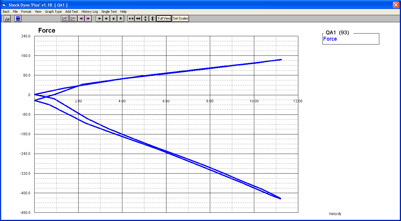
Performance Trends Dyno - QA1 shock tested at 93 deg (produced with v1.1B Plus software)
 (click image to enlarge)
Roehrig tm Dyno - QA1 shock tested at 73 deg
 (click image to enlarge)
Performance Trends Dyno - Penske shock tested at 102 deg (produced with v1.1B Plus software)
 (click image to enlarge)
Roehrig tm Dyno - Penske shock tested at 80 deg
 (click image to enlarge)
People sometimes wonder if a 2.0 HP motor is strong enough for testing some of the high rate shocks used in current circle track racing. The graph below is for a JRI shock on the left front of a CRA Super Late Model, at 2 different and relatively high rebound settings, 7 and 9. You can see we are easily measuring almost 2000 lbs at about 6"/second velocity. (Note: This data actually came from our earlier 1.5 HP dynos, so our 2.0 HP dyno is even better.)

Here's a picture of what happened to one of our shocks we used to test the durability of our Shock Dyno design. Yeah, our dyno is tough.
 click image to enlarge
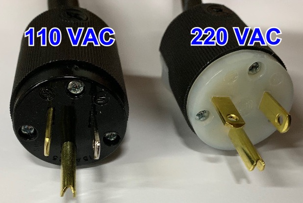 click image of electrical plugs to enlarge. For dynos going outside the
USA, we may include an adapter to the particular plug style in your country.
click image of electrical plugs to enlarge. For dynos going outside the
USA, we may include an adapter to the particular plug style in your country.
You can adjust the stroke for the shock dyno from 0.5" to 2.5". Here are the typical speeds and forces you can generate for these different strokes.
Stroke Max Force Max Speed
0.5 2000* 2.25"/sec
1.0 1800 5.5"/sec
1.5 1300 8"/sec
2.0 900 11"/sec
2.5 700 13"/sec
*2000 lbs is maximum for the load cell and for the shock dyno's design.
What You Need:
Computer with Windows XP, Vista, Windows 7, Windows 8, Windows 10, Windows 11.
More Options and Accessories
- Basic Shock Dyno Software
- Quick start documentation.
- DataMite Mini USB data logger/electronic recorder.
- 2000 lb "S" beam load cell, with optional ranges from 100 to 5000 lbs for nominal charge.
- 3" length/position sensor, with other styles, sizes and lengths available for nominal charge.
- USB Cable (which also powers system, no power supply needed).
- Temp Sensor Optional
- Shut Down Relay and Cabling Optional

The shock dyno kit expects your dyno to use a slider crank (like piston in an engine) or Scotch yoke design to cycle the shock, but does not need a variable speed motor. We very accurately measure the speed of the shock as it goes through its cycle up and down. When it is at the top of its cycle, it has stopped and then changed direction to go back down. As it goes back down, it picks up speed to maximum speed at mid stroke, then slows down when it gets to the bottom of the cycle. Then this whole process is repeated in reverse.
So, as the motor turns at a constant RPM, we can measure the velocity and
force at all points of the cycle, and produce a complete shock dyno graph with
force at all velocities. This makes it very easy for the electrical motor, just
set it to something like 150-300 RPM with a 1" to 3" stroke, get it up
to speed and press F1 on the keyboard. The software records several cycles
and then presents the data.
Jim Butcher's do it yourself (DIY) Shock Dyno built from a small engine with
our retrofit kit (right most picture is doing Mini-Stock Struts)


 click images to enlarge
Jeff Patterson of Dallas TX added our retrofit kit to his motorized (not
pneumatic) Accu-Force tm
shock dyno. The arrows point out our kit components. ![]() to email Jeff if you have questions
to email Jeff if you have questions
![]() to read more about what Jeff had to say
to read more about what Jeff had to say
Brad Milne, Edmonton, Alberta, Canada Can't thank you enough, your
shock dyno software package works perfectly on my home made shock dyno. Two thumbs up! If I had Three I'd give you 3.
![]() to email Brad if you have questions.
to email Brad if you have questions.
 click image to enlarge
Andy Flint, Cranbourne, VIC Australia sent us this video of his
DIY shock dyno.
 click image to enlarge
 ![]() for video
for video
NOTE: Shock Dyno motors with variable frequency drives (VFD or inverter) can emit lots of electrical interference. This may create problems for data loggers and/or your computer, or put noise on sensors. Our shock dyno kit does not need a variable speed motor, and may work better without a variable speed motor.
Accessories:
SDyn-SSAK Three piece "Adapter Kit" for mounting production style shocks on the shock dyno. Kit handles top stud/bottom cross bar type of front shocks, and top cross bar/bottom 5/8" bolt hole rear shocks. Threads are for a shock dyno using 1/2"-20 fine threads, like the Performance Trends' dyno. Other threads available for nominal charge.


 click smaller images to enlarge
SDyn-IRF Shock Dyno infrared (non-contact) temperature sensor with flexible mounting bracket. If you order the retro-fit kit, we typically sell you the DT2-IRA, which is the same sensor but without the bracket. SDyn-IRFB is the part number for the flex bracket without the sensor.

 click images to enlarge
Mounts for motorcycle
forks:
Part number: SDyn-FMT (Shock Dyno Adj. Fork Mount - Top to clamp to body
of fork)
Part number: SDyn-FML (Shock Dyno Adj. Fork Mount - Lower for clamp to an
axle shaft)
 click image to enlarge it
More Information, Movies, Download Demo:
![]() for some movies on setting up and operating the shock dyno Shock Dyno
Movies.
for some movies on setting up and operating the shock dyno Shock Dyno
Movies.
![]() to download a FREE Shock Dyno Demo.
to download a FREE Shock Dyno Demo.
![]() to download the Shock Dyno's User Manual.
to download the Shock Dyno's User Manual.
![]() for pricing.
for pricing.
![]() for financing info on paying on installments.
for financing info on paying on installments.
To email us for a quote for the system to meet your needs ![]() to send us an email.
to send us an email.
To Order:
Call 248-473-9230. Visa and Mastercard accepted. Performance Trends can provide you an "unlocking code" number to activate all features (bring it out of demo mode). When newer versions are released, you can download the latest demo and activate all features with this same "unlocking code".
The "on screen" help explains all features, inputs and outputs.