Performance Trends, Inc.
Producing Quality Computer Tools for Racers and Engine Builders since 1986
Cam Test Stand for Cam Analyzer
Electronics and Encoders for Recording Cam Lobe Measurements
As Seen on TV's Motorhead Garage 
![]() to view clip of show
to view clip of show
Our Cam Test Stand is shown below. It's encoders measure lift to .00004 inches (4 hundredths of one one thousandth of an inch) and cam rotation angle to .05 degrees.
Standard "non-motorized" Stand w
V
Blocks
Motorized Cam Test Stand mounts cam "on centers"
New USB Logger Nov, 2020


![]() to view the Cam Analyzer software page, the
software which runs the Cam Test Stand.
to view the Cam Analyzer software page, the
software which runs the Cam Test Stand.
![]() for
one customer's experience where measuring a new cam saved a lot of time,
money and confusion. We've had lots of customer's relay similar
stories, but Mark put "pen to paper".
for
one customer's experience where measuring a new cam saved a lot of time,
money and confusion. We've had lots of customer's relay similar
stories, but Mark put "pen to paper".
Displayed below are 3 screens showing some of the features of the Cam Analyzer when fitted with our Cam Test Stand.
Main Screen when measuring a lobe. Note that on the main screen, the layout of the cam is displayed so you know exactly which lobe you should be on for the different cylinder numbers, intake and exhaust. Also note that the lobes are graphed immediately with each measurement so lobes which are "out of line" can be quickly checked again.

This comparison report shows critical data for each of the 16 lobes on this cam.
 (Click on image to enlarge it)
This graph shows detailed comparison between all lobes on this cam. You can select to graph only certain lobes or all lobes, and lobes from other cam tests. You can also select to graph lift, velocity, acceleration, and/or jerk.
 (Click on image to enlarge it)
Plus Version of Cam Analyzer
The Plus Version of the Cam Analyzer adds "high tech" several features to our standard program. Prior to version 3.8, most of these features were only useful if you have the complete Cam Test Stand. Now with version 4.3, you can use these features on hand measurements (dial indicator and degree wheel), standard profiles created within Cam Analyzer, and from importing several formats of standard cam files (like Cam Dr tm, Cam Pro Plus tm, S96, Andrews, Comp Cams, Doctor Dr, .svl, .p). These Plus features include:
- Virtual Follower
- Graph Analyze - Find Difference Between Lobes
- Lobe Runout Measurement
- Minimum Required Flat Tappet Diameter Calculation
- Comparison Reports, between different cam files (camshafts)
- Cam Card report
- Indexing the rotary encoder based on dowel pin or keyway location
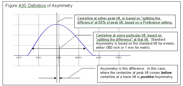
- Measure lobe Asymmetry
- 4 more detailed analysis reports
- Lobe Analysis Report (similar to Don Hubbard's C-PEP report from his "Camshaft reference Handbook")
- Custom Duration Report, and you can include Asymmetry and Overlap
- Seating Velocity Report
- Checking Limits Report
- You can Advance and Retard the cam data after it has been measured
- Watch an animation of the Virtual Follower to see the contact points move, instantaneous Rocker Arm Ratio, etc.
- More Advanced Options for special lobes, like lobes with 2
"bumps" or where you want to view base circle measurements, runout,
etc.
 for info on "2 bumps" option measuring a Briggs & Stratton
cam.
![]() for complete user's manual PDF, where Plus Features are described in
Appendices 4, 5, 6, and 8.
for complete user's manual PDF, where Plus Features are described in
Appendices 4, 5, 6, and 8.
Virtual Follower
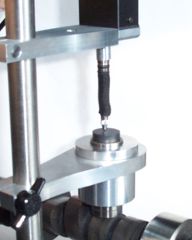
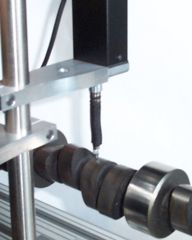
The Virtual Follower feature lets you measure the cam on the stand without using the actual follower used with the cam. You will place the linear encoder's pointer directly on the lobe. See Figures below. The advantage is you don't need the actual follower or the bore adapter of the correct size for the follower. For some valve trains, like Overhead Cam systems with Rocker Arms, the Virtual Follower method is the only method available without installing the cam in the engine or Head.
Using Actual
Follower
Using "Virtual" Follower
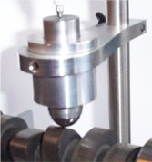
V4.0 lets you use most any roller follower, including
with encoder
pointer
the .750" diameter Universal Roller, pn: CTSUR750
![]() for a graph showing
the significant difference (error) between measuring the lobe with the pointer
only, and how the Virtual Follower simulation converts this data into the true
Cam Profile.
for a graph showing
the significant difference (error) between measuring the lobe with the pointer
only, and how the Virtual Follower simulation converts this data into the true
Cam Profile.
You will enter the measurements for the flat or roller follower, or overhead cam valve train into the program. The software will calculate the resulting valve lift, instantaneous rocker arm ratio, contact point on the follower, and much more. The Virtual Follower feature is currently developed for:
- Flat Tappet Followers (which includes Overhead Cam Direct Acting "Buckets")
- Roller Followers
- Overhead Cam Center Pivot Rocker Arm (input screen shown below)
- Overhead Cam End Pivot Rocker Arm (finger follower, input screen shown below)

 (Click on images to enlarge them)
You can select to use the same or different Virtual Followers on the intake versus the exhaust cam lobes.
Accuracy of Virtual Follower
The graph below indicates the typical accuracy of the Virtual Follower to simulate the actual follower for lift and acceleration. (Acceleration was included as it magnifies differences between lobes.) Note that we could have come up with graphs of better accuracy. We purposely used typical data to show that there will always be some difference between the Virtual Follower results and results measured with the actual follower.
![]() for a "Graph Analyze - Find Difference Between Lobes" report showing the
maximum difference found between these 2 cam measurements (Actual and Virtual
Follower).
for a "Graph Analyze - Find Difference Between Lobes" report showing the
maximum difference found between these 2 cam measurements (Actual and Virtual
Follower). ![]() for a "Lobe Comparison" report showing the difference between these
measurements for Tappet Lift, Duration, Lobe Separation, etc. For most of
these critical measurements, the difference is less than 0.5%. For less
critical measurements, like peak accelerations, the difference is typically
within 2% to 5%.
for a "Lobe Comparison" report showing the difference between these
measurements for Tappet Lift, Duration, Lobe Separation, etc. For most of
these critical measurements, the difference is less than 0.5%. For less
critical measurements, like peak accelerations, the difference is typically
within 2% to 5%.
(Click on image to enlarge it)
Graph Analyze - Find Difference Between Lobes
If you graph 2 cams, an Analyze option is available called Find Difference Between Lobes. This option will automatically advance or retard each corresponding lobe of the second cam to obtain the best match, and then display the max difference between the lobes and how much advance and retard was required. If you have graphed Lift, then the best match for Lift will be found and the max difference in Lift will be displayed. If Velocity and Acceleration are graphed, then the best match for both Velocity and Acceleration will be found and the max difference in Velocity and Acceleration will be displayed.
This feature is very useful for finding how a particular cam has changed
after running in the engine, if a cam is within legal specs for some racing
class, or how similar 2 different cams are. ![]() to see a typical "Find Difference Between Lobes" report for
Lobe Lift only for all 16 lobes.
to see a typical "Find Difference Between Lobes" report for
Lobe Lift only for all 16 lobes. ![]() for a comparison of only 2 lobes, #1 Intake and
Exhaust Lobe Lift and Acceleration.
for a comparison of only 2 lobes, #1 Intake and
Exhaust Lobe Lift and Acceleration.
Indexing the Rotary Encoder
When you measure a cam on the Cam Test Stand, you must choose where the #1 Intake cylinder's lobe will be installed in the engine, typically based on Intake Lobe Centerline. All cam data is accurately measured (duration, lobe separation, lift, overlap, accelerations, etc) and the differences between lobes are identified. However, you would not know if the cam would get installed at this Intake Centerline unless you verified it in the engine.
Note: With redesigns in the Cam Test Stand, the "TDC Checking Bridge" has now been replaced by the much more compact "Narrow Universal Flat Follower", but the process is much the same.
Now we can measure the dowel pin or keyway location of a cam and know how it
is timed in the engine, assuming standard, production timing in the gears.
Using our TDC Checking Bridge, we can precisely measure the dowel pin or keyway
location. Then, knowing how many degrees CW or CCW from TDC it is designed to
be, we can index the rotary encoder precisely. Using this method we can
index the cam to better than 0.5 degrees. (We can provide the
"degrees CW or CCW from TDC" data required for this method for many popular engines, but not
all engines.) For engines for which we don't have this data, you may have
to work out these settings from known cams.

 (Click on images to enlarge them)
The TDC Checking Bridge is sold as an accessory, and adjusts to most any length cam from 12 inches to 24 inches in length (measured from first and last journal bearings). However, you do need the Plus version of the software to access this feature. Longer Bridges are available at an additional cost.
Other Plus Features
Runout is the variation in the base circle radius, where a lower value indicates a higher quality cam. The Minimum Required Flat Tappet Diameter Calculation is an accepted equation based on peak velocity, where larger velocities require a larger flat tappet follower diameter.The Cam Card report displays
critical, measured cam results commonly found on a cam grinder's cam card, shown
below:
 (Click on image to enlarge it)
New Cam Card Options in v4.0
 (Click on image to enlarge it)
Asymmetry Calculation:
More Report Types:
![]() for: Custom Duration (duration, opening, closing, asymmetry at most any cam
or valve lift)
for: Custom Duration (duration, opening, closing, asymmetry at most any cam
or valve lift)
![]() for: Seating Velocity (valve closing velocity at user specified RPMs to
help pick valve Valve Lash)
and estimated lash point
for: Seating Velocity (valve closing velocity at user specified RPMs to
help pick valve Valve Lash)
and estimated lash point
![]() for: Checking Limits (compare a measured lobe to up to 12 specified limits,
like duration at various lifts, lobe separation, max lift, etc.) "Checking Limits" report makes it quick and easy to
check if cams are legal for restricted classes of racing, or are meeting
certain quality control limits.
for: Checking Limits (compare a measured lobe to up to 12 specified limits,
like duration at various lifts, lobe separation, max lift, etc.) "Checking Limits" report makes it quick and easy to
check if cams are legal for restricted classes of racing, or are meeting
certain quality control limits.
Cam Grinder Version of Cam Analyzer
The Cam Grinder version is new for v4.0, and adds several features beyond what the Plus version does. It's features are specially designed for customers who typically grind cams or need to send files to cam grinders for special custom grinds. The Cam Grinder version also gets into more detailed analysis than the typical customer may need. These include:
- Measure cam lobes and keep their absolute timing, and not adjust for lifter bore angle, firing order, etc. It keeps the absolute timing as is present on the actual camshaft, which is more useful to cam grinders. See picture below.
- You can measure absolute lift of the lobes (which will include base circle and runout) and journals if you choose.
- You have many more graphing options and graph data types, including:
- Absolute Lift (This is lift measured from the center line of the cam. If you have a 1.100" diameter base circle and a .400" max tappet lift, you should see approximately .550" of lift on base circle and .950" (.550" + .400") of lift at max lift.)
- Thrust Angle (For a roller cam, this is the angle the contact force is acting on the follower, typically putting some amount of side loading or thrust on the follower.)
- Contact Point (How far from center of the follower has the contact point moved.)
- Radius of Curvature (The radius of curvature at this particular point on the Actual Cam Profile.)
- Raw Cam Data as Measured (This is what the linear encoder measured.)
- Actual Cam Profile (This is what a "knife edge" pointer would have measured. This is the "Raw Cam Data as Measured" but correcting for the radius of the pointer which was doing the measurements. This should be what a cam grinder would have for a design file.)
- Lift Frequency Analysis *
- Acceleration Frequency Analysis. *
- Jerk Frequency Analysis *
* These Frequency Analysis graphs can be done either vs Order Number or RPM Based on the Natural Frequency of a valve spring. The specs for the Natural Frequency of the Valve Spring are contained in the Test/Cam Setup Screen. See picture below.
- Import X and Y data, or polar data (radius, and either radians or degrees) to generate a cam file.
- Input and calculate a valve spring's natural frequency.
- Export a Manufacturing type data file.
- Special Edit and Export Filtering options.
- Include a "Test Piece Picture File" in the test, like a picture
of the cam or other valve train part. This picture can be included in
printouts of the graphs and reports.
Main Screen Graph showing absolute timing
 (Click on image to enlarge it)
Graph showing absolute timing and absolute lift for lobes and journals,
viewed from end of cam (polar coordinates)
 (Click on image to enlarge it)
Graph showing journals with difference exaggerated, viewed from end of cam
(polar coordinates)
 (Click on image to enlarge it)
Cam Grinder Frequency Analysis
 (Click on image to enlarge it)
Cam Grinder Graph Options
 (Click on image to enlarge it)
Cam Grinder Edit Duration Option (figures show increasing durations 15% for
intake and exhaust)
 (Click on images to enlarge them)
Printouts including the Test Piece Picture (page from user's manual)
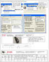 click image to enlarge
![]() for complete user's manual PDF, where Cam Grinder Features are described
in Appendix 6, 7 and 9.
for complete user's manual PDF, where Cam Grinder Features are described
in Appendix 6, 7 and 9.
What You Get:
- Cam stand with adjustable V blocks. 32" length is standard to accommodate cams up to approximately 27-28" long.
- Sliding bracket holding vertical bar holding lifter bore bracket and linear encoder bracket (bar is notched to keep all brackets centered over the cam).
- Linear Encoder with sliding adjustable bracket.
- Lifter bore * and bracket (attaches to Linear Encoder bracket).
- Rotary Encoder with mounting magnet, sleeve and positioning rod.
- DataMite Minu USB data acquisition.
- USB Cable, which provides both data communications and power.
- User's manual.
- Software CD.
- EZ Start Guide.
* Lifter bore is bored to user's requirements for their lifter size, .842" GM is standard. Additional Lifter bore sleeves for different size lifters available at additional cost.
The CTS-WOS (Cam Test Stand without the Stand) consists of item 3 encoder but without the bracket, item 5 encoder but without the mounting parts, and items 6-10.
Accessories:
New Style V Block
(2010)
Old Style V Block (pre 2010)

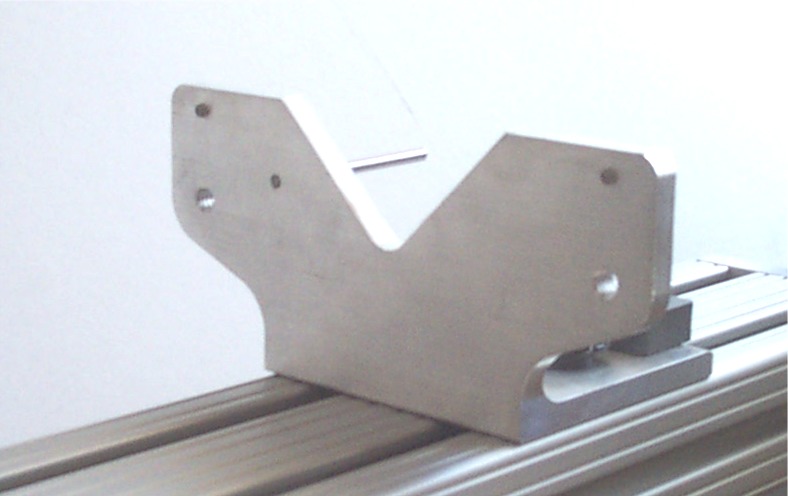
Part of Part Number: CTS-UK Cam Test Stand Update Kit to
bring older CTS up to our current design. This change allows the
linear encoder bracket to slide past the V Block to measure position of keyways
and dowel pins.
indexing grove on the vertical rod and the indexing thumb screw on the CTS-UFH which seats in the groove to keep perpendicular to the cam axis. Note: This part number has now been replaced by the CTS-UFHN Cam Test Stand Narrow Universal Flat Tappet.

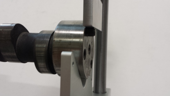
Part Number: CTS-UFHN Cam Test Stand Narrow Universal Flat Tappet with
Indexed Holder, with a 2.0" long x .250" wide flat face. This setup lets you measure most any flat
tappet cam and simulates followers up to 2.0 inches in diameter (the length of
the precision .250" plate held perpendicular to the cam). This can also
be used to measure the position of keyways (with CTS-TDCM2 .250"
magnet in keyway), or dowel pins. Note the indexing screw at front
of lifter bore bracket, and indexing rod which slides in the slot of the lifter
bore to keep things perpendicular to the cam. The narrow, flat edge allows
the follower to ride on timing pins which may stick out of a cam just a few
millimeters. Measuring a timing pin lets you determine the timing of the
cam if you know the location of the pin, or lets you measure the location of a pin
with respect to a cam centerline.
![]() for a movie showing how to locate a dowel pin using the now obsolete "TDC
bridge". Using
the CTS-UFH instead of the bridge would be very similar.
for a movie showing how to locate a dowel pin using the now obsolete "TDC
bridge". Using
the CTS-UFH instead of the bridge would be very similar.
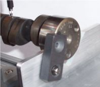
Part Number: CTS-ML Locating magnet, keeps cam aligned accurately on V blocks. Flip down and
its out of the way. Flip up and it keeps cam turning true on the
stand. Magnet slides out of the way if it encounters a dowel pin.
Kit includes magnet, shoulder screw, washer, nylon spacer, template for locating
6-32 hole you drill and tap, and instructions. ![]() for instructions.
for instructions.

Part Number: CTSUR750 Universal .750" roller follower, lets you measure any cam designed for a
.750" diameter roller (typical of most, US V-8 aftermarket rollers).
Sized for a GM .842" ID lifter bore adapter, this includes the follower
only and not the lifter bore adapter.
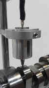
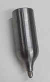 click images to enlarge, tip not included
Part Number: CTS-PTF
Precision Tip Follower provides a method to measure a cam with a very small
radius follower, but avoid side loading wear on the linear encoder (lift
sensor). Side loading can be quite high when measuring lobes with very
steep ramp rates. The follower comes with 4-48 threads to accept our
CTS-PT, or probes you can provide.
Note: Current design may look slightly different but function the
same.
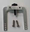

 click images to enlarge
Part Number: CTS-VBC V-Block
Clamp, holds short cams firmly on the V Block, shown installed with Adjustable V
Block. Short cams with the linear encoder attached to the end will tend to
tip off the V Blocks, and this clamp holds the cam in place. It has a
soft, nylon tip to provide smooth rotation and not damage the journal.

 click images to enlarge
Part Number: CTS-RHD8 Rotary Encoder mount we developed for the
Harley Davidson Milwaukee 8 cams. It is steel and has somewhat higher
precision than the "Flat Mount" below, and can be more
universal. It has a steel tapered pin of .250" (6.4 mm) diameter, and
a magnet .375" (9.5mm) ID and .750" (19mm) OD . So if your cam
has a small hole in the end of less than .250" and an ID of less than
.650" (16.5mm) and an OD of more than .400" (10mm), this will work
well for you.
Standard Flat Mount 1.00"
magnet
Small Flat Mount .75" magnet


 click images to enlarge
Part Number: CTS-RMF and CTS-RMFI
Cam Test Stand Rotary Encoder Flat Mount and Insert will attach the rotary
encoder to cams without a flat face on one of the ends. These are
typically motorcycle cams. ![]() for instructions.
for instructions.
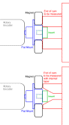
Click on image above to understand the information we need for this flat mount
insert. The magnets come in 2 sizes, small is .38" ID with .750"
OD, or standard is .50" ID with 1.00" OD. We can make the
inserts to most any size, to accommodate either straight or tapered holes in the
end of your cams. In the picture of the Small Flat Mount above, the insert
is quite small, a 5.5 mm diameter. You need to specify the outside diameter and thickness
of the insert (green in picture). The insert does not need to fit perfectly, so
specify an outside diameter slightly smaller than you think you need. If the
rotary encoder is slightly off center, it does not have a significant effect on
the data.
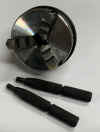


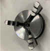
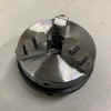 click images to enlarge
Part Number: CTS-RECM Rotary
Encoder Chuck Mount, requires the CTS-EVB above to provide
clearance. This mount for the rotary encoder can work for cams with very
large or very small centering holes, or very small journals on the ends of the
cam. This chuck can grab either and outside diameter or inside diameter,
and can be more universal than the magnetic mounting methods we offer. The
jaws can open up to accommodate cam journals as large as 2.80" or larger.
Jaws flipped to grab an inside diameter can go as small as .875" inside
diameter.
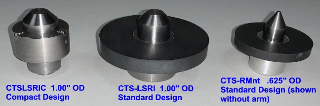
Part Number: CTS-LSRI and CTSLSRIC Larger diameter rotary encoder index
(1.00") and
magnet/bore to accommodate cams with larger than .625" holes in their ends.
The Compact Design allows for more clearance around index, so it fits on the Cam
Test Stand better for more cam designs.
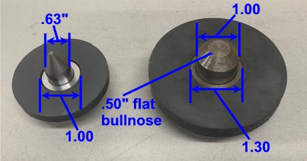
Here's some measurements so you can decide which may work better on your
cams. The ID of the part of the cam to locate the center (pointy part)
should be smaller than the OD of the centers shown in this picture. The OD
of the end of the cam can not be smaller than the ID of the magnet.
Otherwise there is no magnet to attach to the end of the cam. The CTSLSRIC
compact design has the magnets closer to the 1.00" center compared to the
larger design shown in this picture. The 1.30" measurement is
approximately 1.10", so it can accommodate a cam with a smaller OD.


 click images to enlarge
Part Number: CTS-REBF Magnetic rotary encoder mounting adapter for
Briggs & Stratton flatheads, with .75" diameter journals. The
Briggs cam in the picture is being measure with the CTS-REBF and our Universal
Flat follower (CTS-UFN). The standard V Blocks typically provide enough
clearance for the gear on the cam. To accurately measure the intake lobe
with the "EZ Pull" compression relief on the intake closing ramp, you
need to set the Option of "Cam Lobe may have 2 bumps". This
option is only in the Plus or Cam Grinder version of the software.
![]() for
a movie "Installing-rotary-encoder-magnetic-mount.mp4" showing
how to install the rotary encoder with magnetic mount on the end of a typical
camshaft.
for
a movie "Installing-rotary-encoder-magnetic-mount.mp4" showing
how to install the rotary encoder with magnetic mount on the end of a typical
camshaft.
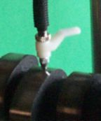
Part Number: CTS-LEH Linear Encoder lift handle, provides an easy way
to lift the linear encoder probe. This is especially handy when not using
a follower, but measuring the lobe directly for the Virtual Follower feature.
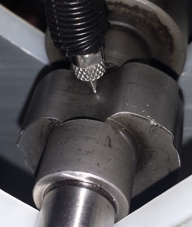
Part Number: CTS-PT Precision 0.047 inch diameter tip for linear encoder. This is required
for measuring very aggressive, inverted flank (concave) profiles.
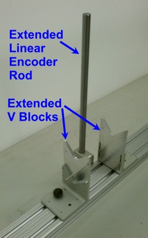
Part Number: CTS-EVB Extended Height V Block Kit, includes 2 V Block
Extensions (requires "New Style V Block
(2010)" shown above) and extended length Linear Encoder
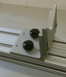
Part Number: CTS-AVB Adjustable V Block lets you level out the cam
when the journal on one end can be significantly different than the other
end. Note: A slight difference in cam height from end to end (slight
slope of the camshaft on the stand) is not critical for most measurements,
because the encoder is "zero'd out" by the software for each lobe
measurement.

Part Number: CTS-MC This option adds a motor to turn the cam at a
slow, controlled rate, and for mounting the cam "on centers".
This can provide for more accurate measurements, especially for acceleration and
jerk measurements.
 click image to enlarge detail of pointed center for CTS-MC to see how well it would work
for your particular cams. Center is .900" diameter with 60 deg taper.
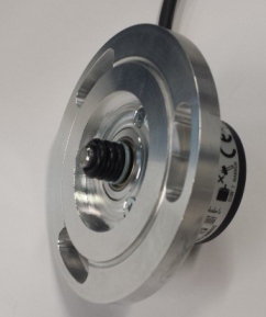
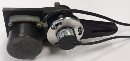
Part Number: CTS-RECA This Rotary Encoder Cam Pro Plus Adapter plate
lets you mount the Performance Trends rotary encoder into the Cam Pro Plus
mounting bracket. This provides more options to ensure you can completely
convert your Cam Pro Plus hardware to Performance Trends software and
electronics.
 click image to enlarge
Part Number: CTS-RMnt
Rotary Encoder Mounting Kit lets you magnetically mount and center the
rotary encoder to the end of your cam. This is a popular option for
customers who want to build their own stand with V blocks.
 click images to enlarge
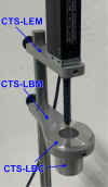
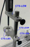
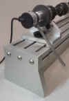
Part Number: CTS-LEM linear encoder mounting arm CTS-LBM lifter
bore mount CTS-LBC lifter bore (custom size) CTS-LESR linear
encoder sensor rod These can be ordered as replacement parts
or for you to adapt to your own DIY cam test stand.
 click image to enlarge
Part Number: CTS-xxHD Heavy
Duty Cam Test Stand option, where xx is the length of the stand in inches.
This option is for very long, or very large (journals over 3" diameter), or very heavy cams which can weigh up to 100 lbs or
more. It includes larger base extrusion, roller bearings instead of V
blocks, and other heavy duty brackets.

Part Number: CTS-WOS This is a complete test stand, but without the
stand. This is a good choice for people who want to build their own
hardware. The system includes the precision linear and rotary sensor,
Black Box II logger, and basic Cam Analyzer software. Please note that
building a cam test stand is not as simple as you may first think. We have
learned over the years the items which are important to make the stand both easy
to use and keep the measurements as accurate as possible.
Ask about other custom options which include:
- 38 and 48 inch long stands for cams up to 34 or 44 inches respectively. Combined with the CTS-xxHD Heavy Duty Cam Test Stand option, we've made stands over 100" long.
- Lifter Bore Adapters to accommodate various lifter diameters (Note lifter diameters greater than approximately 34 mm require a special, larger lifter bore bracket.)
![]() to return to the main Cam Analyzer page.
to return to the main Cam Analyzer page.
![]() for prices of the
Cam Test Stand and accessories.
for prices of the
Cam Test Stand and accessories.
![]() for narrated demo movies explaining program features
for narrated demo movies explaining program features
![]() for info
on Cam Test Stand Assembly
for info
on Cam Test Stand Assembly
![]() for tips on producing repeatable results
for tips on producing repeatable results
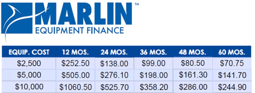
Financing can make your larger investment very affordable. Here's a typical rate schedule (June 2018).
